The CoCo mail list has recently had a bit of discussion about replacing or repairing CoCo keyboards, including the feasibility of having new CoCo compatible keyboards made. The CoCo 2 and CoCo 3 keyboards used the same construction that most PC keyboards use today: a mylar flexible printed circuit. Sometimes this mylar becomes brittle and cracks, breaking the circuit traces.
In this context a question came up about whether or not a single keyboard could be produced that would be compatible with all three CoCo models. I knew that this could work, given an appropriate connector adapter, since I have a CoCo 3 keyboard in my original Color Computer 1.

The holes are from when I had a 1/2 height floppy drive mounted on the top of the computer and an un-cased disk controller inside, underneath the motherboard. Seemed to make sense at the time.
 Back in the early ’90s, it was all the rage to mount CoCo 3s in PC mini tower cases. To understand why, you need to realize how many cables and power supplies and external boxes a fully equipped CoCo system of the day had. There was the computer itself, possibly a Multi-Pak Interface, a floppy drive controller with a cable running to a drive housing with its own power supply, maybe a hard drive controller and cable with yet another box and power cord, a serial interface with a cable running to a modem and all its associated power and phone cables, and maybe a parallel port attached to a printer. If any of this stuff got bumped it could ruin your day, at a minimum.
All of it could be packed into a single case, and run off a single power supply. Adapters were available that allowed one to use a PC/XT keyboard, so a rig like this could be used without the built-in CoCo keyboard. When i wanted to add a SCSI hard drive to my CoCo 3 system, I went this route. I stuck the CoCo motherboard, a Disto Super Controller II with 4-in-1 board (1 serial, 1 parallel, 1 SCSI interface, 1 real-time clock), a 5.25″ and a couple 3.5″ floppy drives, and in its first configuration, a 10M MFM hard drive with a SCSI/ST-506 host adapter board, all into a mini tower case, with serial and parallel ports, joystick connectors, and an XT keyboard jack mounted neatly on the rear.
This left me with a CoCo 3 case, which I eventually used to house my CoCo3FPGA, and a spare CoCo 3 keyboard. The original CoCo had a less-than-stellar “chiclet keyboard“, and mine wasn’t working very well anymore. So I decided to try to install the CoCo 3 keyboard in the CoCo 1. The biggest hurdle was the fact that the connectors were different. The CoCo 3 motherboard has a thin female connector that the mylar, reinforced with a stiff piece of sticky-backed clear plastic, slides into. The original Color Computer had a single row of bent header pins on both the motherboard and the keyboard. It used a short length of ribbon cable with half the usual conductor density (i.e. it has half the number of wires in the same width as, say, a floppy drive cable) with connectors on each end. Importantly though, the conductors are arranged with the same row and column connections, so you only have to bridge the connector gap, not rearrange the wiring, to get a Coco 2 or 3 keyboard attached to the original CoCo, or put a “chiclet keyboard” on a later machine for whatever perverse and inscrutable reason.
It’s been over two decades since I did this, but examining it now, it looks as if what I did was to remove one of the connectors from the CoCo 1’s keyboard cable, and attach it to every-other conductor of a cut-off floppy cable, with a 34-pin IDC card edge connector on the other end.
 There are a couple more tricks necessary for getting this to work. The CoCo’s keyboard connector has 16 (well, really just 15, but spaced for 16) conductors, while the card edge connector has two rows of 17 pins. The other issue is that the card edge connector is intended for a thick circuit board, not a thin strip of mylar. Finally, you need to to make sure you connect the right side of the mylar to the correct row of contacts on the connector.
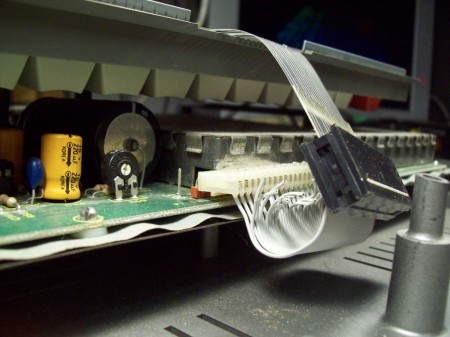 I simply cut off a bit of printed circuit board to fill the thickness of the connector and press the mylar firmly against the contacts. Then it was just a matter of getting things lined up to the correct pins.
Obviously this does not solve the problem of aging and cracking mylar, but this keyboard seems to have held up pretty well so far. I’d love to see a new run of CoCo compatible keyboards, and yes, they could work on any CoCo, especially if some kind of connector adapter could be come up with. If not, one could do something like what I’ve done here.

If you try this, I recommend finding a different place to split the conductors with an X-acto knife. What was I thinking?
Tags: Connector, Keyboard, Maintenance, Preservation

Leave a comment